
Alpine Ainet/Aux RCA input switcher not working: 2000 XK8 Premium Sound
#21
 04-12-2011, 03:05 PM

Veteran Member
The noise level is pretty high, and seems independent of what the inputs are doing on the PIE.
I don't think the shielding of the RCA cables would make much of a difference I had the same noise level when everything was loosly laying in the trunk away from the rest of the vehicle wiring as I have now with it routed properly.
I read about cutting the jumpers in the preamp, but I have doubts about that helping since the noise is there without anything connected.
I suppose what I could try is shorting the RCA inputs to the PIE. If the + and - are connected directly together there will be no signal input (noise or otherwise) to the PIE possible. The trick would be to have an input to cause the device to switch, then remove it and install the short before it switches back. IF there is still noise with that, then the noise source MUST be within the PIE device.
I am starting to suspect that maybe the AI-net pigtail might be miswired, IE the right colors are soldered in the right places on the PCB, but aren't in the right place on the connector.
I am a bit stumped by this if the PIE itself turn out to be generating all this noise...your configuration now sound essentially identical to mine, which works fine. If all else fails, you can PM me and arrange to send me your AI-Net adapter and I can compare it with mine.
#22
04-18-2011, 08:32 PM

As you may remember I actually have two of the PIE switchers. I tried the other one (the used / smashed one) today, and it is MUCH quieter. I can still hear some of the noise, but only if I pause the MP3 player. So I think there is something wrong with the new PIE switcher.
I plan to use the PAC amp even though the noise is greatly reduced now in order to even out the volume between sources because the MP3 player is somewhat quieter than the AM/FM or CD changer.
I plan to use the PAC amp even though the noise is greatly reduced now in order to even out the volume between sources because the MP3 player is somewhat quieter than the AM/FM or CD changer.
#23
04-18-2011, 09:33 PM
Veteran Member
As you may remember I actually have two of the PIE switchers. I tried the other one (the used / smashed one) today, and it is MUCH quieter. I can still hear some of the noise, but only if I pause the MP3 player. So I think there is something wrong with the new PIE switcher.
I plan to use the PAC amp even though the noise is greatly reduced now in order to even out the volume between sources because the MP3 player is somewhat quieter than the AM/FM or CD changer.
I plan to use the PAC amp even though the noise is greatly reduced now in order to even out the volume between sources because the MP3 player is somewhat quieter than the AM/FM or CD changer.
http://www.radioshack.com/product/in...ductId=2062214
Last edited by WhiteXKR; 04-18-2011 at 09:36 PM. Reason: fixed link
#24
05-01-2011, 12:45 AM
Senior Member
Hi, not sure who might be following this thread, but wanted to report on my sound issues with the PIE AI/AUX switcher as they seem the same as some others have had with some versions and maybe this is why.
Situation:
I tried the PIE AUX switcher on my '02 XJR with CD/Nav/Premium sound and while the CD worked, when it switched to the AUX source, I only got weak and distorted sounds.
I tried the device in line as follows.
As others have commented, I confirmed that the insert point needs to be inline between the CD and the Amp so that the NAV to head audio and CD/AUX audio would be routed and muted properly as most f the audio goes through the AMP and the AI NET is for control, but I still had to fix the AUX AUDIO that was distorted and weak.
INSIGHT!
When I plugged the AUX switcher into the AINET line, I was using the plugs and cables that fitted (M>F, F>M), Jag cable to PIE AI socket and PIE AI cable to Jag, but when looking closer, I saw that the Jag AINET cable was plugging into the AUX switcher OUTPUT socket and the AUX cable is the output signal.
This is reversed, and means that the AUX audio was being switched to the CD rather than to the AMP.
To fix this I would have needed two AI M-F adapters but these are not so easy to find. Instead, I did a little surgery on the PIE AI switcher to reverse the AI output and inputs. This involved cutting two traces and running two wires to reverse the Audio from socket to plug.
Now the AI Socket was an input and the AI flying lead was the output and could connect in line correctly and switch correctly.
Now, the audio levels were fine, the AUX switched and all was quiet with no whine or distortion.
The device still has to go in the trunk, but I will run the RCA leads out now forward to the console and the T605 bluetooth, not so much fun, but I think OK.
Hope this may help someone and I can supply photos if desired of the PI AUX mod. You would need to be able to solder to some small circuit pads.
Situation:
I tried the PIE AUX switcher on my '02 XJR with CD/Nav/Premium sound and while the CD worked, when it switched to the AUX source, I only got weak and distorted sounds.
I tried the device in line as follows.
- AINET cable to Head unit (Ideal as it would allow easy interface to bluetooth audio streaming from T605) - CD OK, AUX NO GO (CD Plays still)
- NAV to AMP CD OK, AUX NO GO (CD plays still)
- CD to Amp CD OK, AUX weak and distorted
As others have commented, I confirmed that the insert point needs to be inline between the CD and the Amp so that the NAV to head audio and CD/AUX audio would be routed and muted properly as most f the audio goes through the AMP and the AI NET is for control, but I still had to fix the AUX AUDIO that was distorted and weak.
INSIGHT!
When I plugged the AUX switcher into the AINET line, I was using the plugs and cables that fitted (M>F, F>M), Jag cable to PIE AI socket and PIE AI cable to Jag, but when looking closer, I saw that the Jag AINET cable was plugging into the AUX switcher OUTPUT socket and the AUX cable is the output signal.
This is reversed, and means that the AUX audio was being switched to the CD rather than to the AMP.
To fix this I would have needed two AI M-F adapters but these are not so easy to find. Instead, I did a little surgery on the PIE AI switcher to reverse the AI output and inputs. This involved cutting two traces and running two wires to reverse the Audio from socket to plug.
Now the AI Socket was an input and the AI flying lead was the output and could connect in line correctly and switch correctly.
Now, the audio levels were fine, the AUX switched and all was quiet with no whine or distortion.
The device still has to go in the trunk, but I will run the RCA leads out now forward to the console and the T605 bluetooth, not so much fun, but I think OK.
Hope this may help someone and I can supply photos if desired of the PI AUX mod. You would need to be able to solder to some small circuit pads.
#25
05-01-2011, 06:20 AM
Veteran Member
Hi, not sure who might be following this thread, but wanted to report on my sound issues with the PIE AI/AUX switcher as they seem the same as some others have had with some versions and maybe this is why.
Situation:
I tried the PIE AUX switcher on my '02 XJR with CD/Nav/Premium sound and while the CD worked, when it switched to the AUX source, I only got weak and distorted sounds.
I tried the device in line as follows.
INSIGHT!
When I plugged the AUX switcher into the AINET line, I was using the plugs and cables that fitted (M>F, F>M), Jag cable to PIE AI socket and PIE AI cable to Jag, but when looking closer, I saw that the Jag AINET cable was plugging into the AUX switcher OUTPUT socket and the AUX cable is the output signal.
This is reversed, and means that the AUX audio was being switched to the CD rather than to the AMP.
To fix this I would have needed two AI M-F adapters but these are not so easy to find. Instead, I did a little surgery on the PIE AI switcher to reverse the AI output and inputs. This involved cutting two traces and running two wires to reverse the Audio from socket to plug.
Now the AI Socket was an input and the AI flying lead was the output and could connect in line correctly and switch correctly.
Now, the audio levels were fine, the AUX switched and all was quiet with no whine or distortion.
The device still has to go in the trunk, but I will run the RCA leads out now forward to the console and the T605 bluetooth, not so much fun, but I think OK.
Hope this may help someone and I can supply photos if desired of the PI AUX mod. You would need to be able to solder to some small circuit pads.
Situation:
I tried the PIE AUX switcher on my '02 XJR with CD/Nav/Premium sound and while the CD worked, when it switched to the AUX source, I only got weak and distorted sounds.
I tried the device in line as follows.
- AINET cable to Head unit (Ideal as it would allow easy interface to bluetooth audio streaming from T605) - CD OK, AUX NO GO (CD Plays still)
- NAV to AMP CD OK, AUX NO GO (CD plays still)
- CD to Amp CD OK, AUX weak and distorted
INSIGHT!
When I plugged the AUX switcher into the AINET line, I was using the plugs and cables that fitted (M>F, F>M), Jag cable to PIE AI socket and PIE AI cable to Jag, but when looking closer, I saw that the Jag AINET cable was plugging into the AUX switcher OUTPUT socket and the AUX cable is the output signal.
This is reversed, and means that the AUX audio was being switched to the CD rather than to the AMP.
To fix this I would have needed two AI M-F adapters but these are not so easy to find. Instead, I did a little surgery on the PIE AI switcher to reverse the AI output and inputs. This involved cutting two traces and running two wires to reverse the Audio from socket to plug.
Now the AI Socket was an input and the AI flying lead was the output and could connect in line correctly and switch correctly.
Now, the audio levels were fine, the AUX switched and all was quiet with no whine or distortion.
The device still has to go in the trunk, but I will run the RCA leads out now forward to the console and the T605 bluetooth, not so much fun, but I think OK.
Hope this may help someone and I can supply photos if desired of the PI AUX mod. You would need to be able to solder to some small circuit pads.
Just wondering though, before your mod., when you connected between the nav. and amp, did you check to see whether the AI-AUX was muting the radio instead of the CD? This is the way it works on an XKR with premium and nav.
For standard audio, I think your solution is definitely the way to go. I would be interested in your photos.
#26
05-01-2011, 08:31 AM

...
Situation:
I tried the PIE AUX switcher on my '02 XJR with CD/Nav/Premium sound and while the CD worked, when it switched to the AUX source, I only got weak and distorted sounds.
I tried the device in line as follows.
As others have commented, I confirmed that the insert point needs to be inline between the CD and the Amp so that the NAV to head audio and CD/AUX audio would be routed and muted properly as most f the audio goes through the AMP and the AI NET is for control, but I still had to fix the AUX AUDIO that was distorted and weak.
INSIGHT!
When I plugged the AUX switcher into the AINET line, I was using the plugs and cables that fitted (M>F, F>M), Jag cable to PIE AI socket and PIE AI cable to Jag, but when looking closer, I saw that the Jag AINET cable was plugging into the AUX switcher OUTPUT socket and the AUX cable is the output signal.
This is reversed, and means that the AUX audio was being switched to the CD rather than to the AMP.
To fix this I would have needed two AI M-F adapters but these are not so easy to find. Instead, I did a little surgery on the PIE AI switcher to reverse the AI output and inputs. This involved cutting two traces and running two wires to reverse the Audio from socket to plug.
Now the AI Socket was an input and the AI flying lead was the output and could connect in line correctly and switch correctly.
Now, the audio levels were fine, the AUX switched and all was quiet with no whine or distortion.
The device still has to go in the trunk, but I will run the RCA leads out now forward to the console and the T605 bluetooth, not so much fun, but I think OK.
Hope this may help someone and I can supply photos if desired of the PI AUX mod. You would need to be able to solder to some small circuit pads.
Situation:
I tried the PIE AUX switcher on my '02 XJR with CD/Nav/Premium sound and while the CD worked, when it switched to the AUX source, I only got weak and distorted sounds.
I tried the device in line as follows.
- AINET cable to Head unit (Ideal as it would allow easy interface to bluetooth audio streaming from T605) - CD OK, AUX NO GO (CD Plays still)
- NAV to AMP CD OK, AUX NO GO (CD plays still)
- CD to Amp CD OK, AUX weak and distorted
As others have commented, I confirmed that the insert point needs to be inline between the CD and the Amp so that the NAV to head audio and CD/AUX audio would be routed and muted properly as most f the audio goes through the AMP and the AI NET is for control, but I still had to fix the AUX AUDIO that was distorted and weak.
INSIGHT!
When I plugged the AUX switcher into the AINET line, I was using the plugs and cables that fitted (M>F, F>M), Jag cable to PIE AI socket and PIE AI cable to Jag, but when looking closer, I saw that the Jag AINET cable was plugging into the AUX switcher OUTPUT socket and the AUX cable is the output signal.
This is reversed, and means that the AUX audio was being switched to the CD rather than to the AMP.
To fix this I would have needed two AI M-F adapters but these are not so easy to find. Instead, I did a little surgery on the PIE AI switcher to reverse the AI output and inputs. This involved cutting two traces and running two wires to reverse the Audio from socket to plug.
Now the AI Socket was an input and the AI flying lead was the output and could connect in line correctly and switch correctly.
Now, the audio levels were fine, the AUX switched and all was quiet with no whine or distortion.
The device still has to go in the trunk, but I will run the RCA leads out now forward to the console and the T605 bluetooth, not so much fun, but I think OK.
Hope this may help someone and I can supply photos if desired of the PI AUX mod. You would need to be able to solder to some small circuit pads.
Please post photos of the mod!
A related question to everyone else listening on this thread:
On my XKR the sound is very '2 dimensional', and all at the front of the car. I'd prefer to have the sound more 'mid' car, or even behind me.
I discovered that the 'fade' (front to back) is disabled on the head unit, and the cars handbook says this is normal on an XKR with premium sound (because the rear speakers are replaced with subwoofers(?) - which are clearly working). It warns that enabling the fade won't give much of an improvement.
What's the best way to resolve this? I see some of you have been fitting other speakers in the back, but wasn't sure whether this was the reason. Would replacing the rear speakers with something with a good all round frequency response work, or does the amp only send the base out to the rear speakers?
-Steve
PS I had a 'green shower' this week (after putting less than 300 miles on the car ), so plan to at least put some of the cables in place while I have the interior in pieces to fix this)
#27
05-08-2011, 01:51 AM
Senior Member
Thanks...this is great input!
Just wondering though, before your mod., when you connected between the nav. and amp, did you check to see whether the AI-AUX was muting the radio instead of the CD? This is the way it works on an XKR with premium and nav.
For standard audio, I think your solution is definitely the way to go. I would be interested in your photos.
After cutting two tracks on the PI board and routing one side to the cable and the other side to the socket, reversing the audio, things worked fine and the AI unit now switches to the AUX and overrides either the tape or the Radio.
The audio units sound level is same as Radio or Tape.
Doing a the head unit is much easier than routing sound through from the trunk. I am using the Motorola T605 so can now stream music from Pandora radio and the iPod as desired.
Hope this helps others interface sound in non destructively.
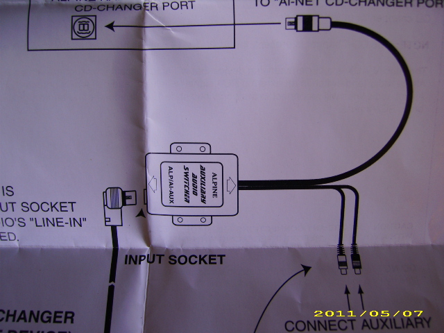
Original Diagram showing connections that are the wrong way for what I needed.
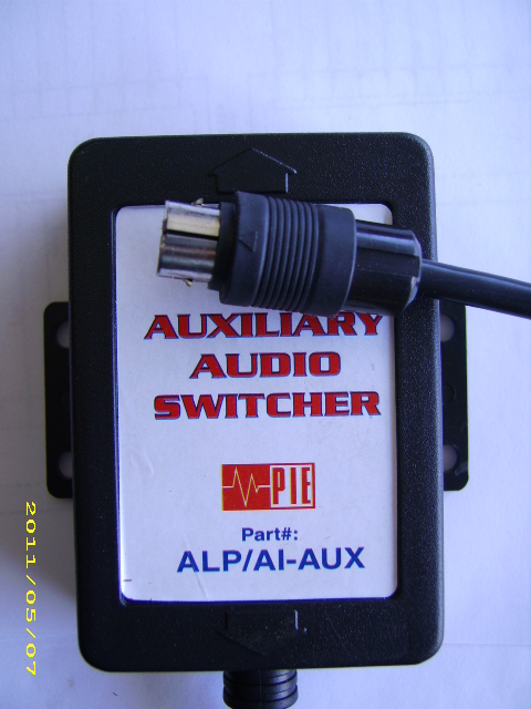
This is the PIE unit
Unsolder the two wires that are the audio out from the cable and add extensions.

Cut two tracks that are the audio in that go to the socket.

Add extensions from the socket that is now audio out to where the two audio wires from the cable attached.
Add the cable extensions to the capacitor side of the two tracks that were cut. This is now audio IN from the cable.
Added a 3.5 mm cable in the console for audio in.
#28
05-08-2011, 10:23 AM
Veteran member
Originally Posted by the fixer
A related question to everyone else listening on this thread:
On my XKR the sound is very '2 dimensional', and all at the front of the car. I'd prefer to have the sound more 'mid' car, or even behind me.
I discovered that the 'fade' (front to back) is disabled on the head unit, and the cars handbook says this is normal on an XKR with premium sound (because the rear speakers are replaced with subwoofers(?) - which are clearly working). It warns that enabling the fade won't give much of an improvement.
What's the best way to resolve this? I see some of you have been fitting other speakers in the back, but wasn't sure whether this was the reason. Would replacing the rear speakers with something with a good all round frequency response work, or does the amp only send the base out to the rear speakers?
-Steve
The amplifier sends out the leads to the speakers already crossed over (internally) so to get the most from your new coax units, you'll need to mix the front tweets, mids (in dash) and the mid bass in the doors...not easily done, but I'm sure if you're resourceful, you'll find a way. any chance the 'rear' channel from the amplifier still has full signal output available, as would be used by the coupe systems? That would be perfect for this addition...and not screw with the subwoofer output.
#29
05-09-2011, 08:36 PM
OK I decided to dive back into mine and see if I could find out why one of my PIE switchers is working and the other not, as well as to look at the reverse connection situation mentioned by dsetter.
First on my 2002 XKR simply plugging the AI net switcher between the CD changer, and amp is reversed as he says above.
Plugging it between the Nav and Amp is the correct orientation, and works in my car. Plugging it between the head unit and Nav also appears to be the correct orientation, however I did not actually try that last combination.
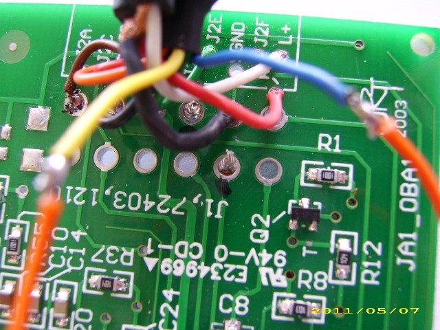
Next I popped the cases off both of my PIE switchers to see if one was wired incorrectly, hopefully explaining why one workedand the other doesn't. But, both seem to have the pigtail wired identically, as below.

AI pin - pigtail wire color - signal name - PCB location shown on right side of board below.
1 - Brown - Accessory - J2A
2 - Purple - Data bus Gnd - J2B
3 - Orange - Data Bus - J2C
4 - Yellow - Right Signal Output- J2D
5 - Green - Signal Ground Output - J2E
6 - Blue - Left Signal Output - J2F
7 - Red - Batt - J2G
8 - Black - Ground - J2H
So everything seems in order there.
In regard to Jagosaurus posting on the signal ground being wired incorrectly. ( https://www.jaguarforums.com/forum/x...chering-49637/ ) I dug deeper into that because the signal grounds indeed are not all connected together as you might expect. The signal grounds all appear to run to an IC instead.
I pulled up the data sheet for this IC to see what it does ( http://www.datasheet4u.net/download.php?id=109176 ) Essentially it is a three input, 2 way switch. There are three outputs, A, B, and C, the input connected to those respective outputs are ax or ay, bx or by, and cx, or cy. These three pairs can all be selected individually, but in our case they are all selected together - so either all of the x inputs (female AI-net connector input), or all of the y inputs (RCA cable pair) are connected to the signal lines of the pigtail.
Selector lines A, B and C are all connected so they all switch together. When the signal to these is all 0;
ax (left ai-net in) is connected to A (left ai-net out)
cx (right AI-net in) is connected to C (right AI-net out)
bx (AI-net in signal ground) is connected to B (AI-net out signal ground)
When there is a signal on the RCAs, transistor Q2 switches the inputs;
ay (left RCA) is connected to A (left ai-net out)
cy (right RCA) is connected to C (right AI-net out)
bx (RCA signal ground) is connected to B (AI-net out signal ground)
So the signal ground is switched along with the left and right signals. I assume this is done to isolate noise on the grounds.
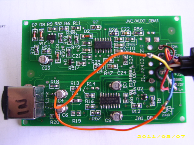
I'm going to borrow a picture here;

The switching IC in question is at the bottom of the picture between C8 and C9 (filter capacitors on the RCA right and left signal inputs.)
C4 and C6, where the wires are soldered, are the filter caps for the AI-net signal inputs.
Finally, why is one of my units working, and the other not? R57 in the non-working unit is smoked! This is a 0 ohm resistor that connects the RCA signal ground to the PCB ground - thus explaining why this unit is noisy when using the RCAs. My "working unit" was damaged, and the C8 filter capacitor on the RCA left signal input is smashed flat and measures as a dead short - the signal still gets through to the IC, but there will be no filtering if I get a DC offset on that input.
So for now I plan to replace the 0 ohm resistor on the board that wasn't smashed. Though I'm not sure what fried it, maybe the reverse connection between the changer and amp I tried originally?
I'm also more anxious to get this finalized because my changer just decided to tell me "No disc" whenever I try to use it now, leaving me with only AM, and FM to listen to.
First on my 2002 XKR simply plugging the AI net switcher between the CD changer, and amp is reversed as he says above.
Plugging it between the Nav and Amp is the correct orientation, and works in my car. Plugging it between the head unit and Nav also appears to be the correct orientation, however I did not actually try that last combination.
Next I popped the cases off both of my PIE switchers to see if one was wired incorrectly, hopefully explaining why one workedand the other doesn't. But, both seem to have the pigtail wired identically, as below.
AI pin - pigtail wire color - signal name - PCB location shown on right side of board below.
1 - Brown - Accessory - J2A
2 - Purple - Data bus Gnd - J2B
3 - Orange - Data Bus - J2C
4 - Yellow - Right Signal Output- J2D
5 - Green - Signal Ground Output - J2E
6 - Blue - Left Signal Output - J2F
7 - Red - Batt - J2G
8 - Black - Ground - J2H
So everything seems in order there.
In regard to Jagosaurus posting on the signal ground being wired incorrectly. ( https://www.jaguarforums.com/forum/x...chering-49637/ ) I dug deeper into that because the signal grounds indeed are not all connected together as you might expect. The signal grounds all appear to run to an IC instead.
I pulled up the data sheet for this IC to see what it does ( http://www.datasheet4u.net/download.php?id=109176 ) Essentially it is a three input, 2 way switch. There are three outputs, A, B, and C, the input connected to those respective outputs are ax or ay, bx or by, and cx, or cy. These three pairs can all be selected individually, but in our case they are all selected together - so either all of the x inputs (female AI-net connector input), or all of the y inputs (RCA cable pair) are connected to the signal lines of the pigtail.
Selector lines A, B and C are all connected so they all switch together. When the signal to these is all 0;
ax (left ai-net in) is connected to A (left ai-net out)
cx (right AI-net in) is connected to C (right AI-net out)
bx (AI-net in signal ground) is connected to B (AI-net out signal ground)
When there is a signal on the RCAs, transistor Q2 switches the inputs;
ay (left RCA) is connected to A (left ai-net out)
cy (right RCA) is connected to C (right AI-net out)
bx (RCA signal ground) is connected to B (AI-net out signal ground)
So the signal ground is switched along with the left and right signals. I assume this is done to isolate noise on the grounds.
I'm going to borrow a picture here;
The switching IC in question is at the bottom of the picture between C8 and C9 (filter capacitors on the RCA right and left signal inputs.)
C4 and C6, where the wires are soldered, are the filter caps for the AI-net signal inputs.
Finally, why is one of my units working, and the other not? R57 in the non-working unit is smoked! This is a 0 ohm resistor that connects the RCA signal ground to the PCB ground - thus explaining why this unit is noisy when using the RCAs. My "working unit" was damaged, and the C8 filter capacitor on the RCA left signal input is smashed flat and measures as a dead short - the signal still gets through to the IC, but there will be no filtering if I get a DC offset on that input.
So for now I plan to replace the 0 ohm resistor on the board that wasn't smashed. Though I'm not sure what fried it, maybe the reverse connection between the changer and amp I tried originally?
I'm also more anxious to get this finalized because my changer just decided to tell me "No disc" whenever I try to use it now, leaving me with only AM, and FM to listen to.
#30
05-09-2011, 08:42 PM
Veteran Member
OK I decided to dive back into mine and see if I could find out why one of my PIE switchers is working and the other not, as well as to look at the reverse connection situation mentioned by dsetter.
First on my 2002 XKR simply plugging the AI net switcher between the CD changer, and amp is reversed as he says above.
Plugging it between the Nav and Amp is the correct orientation, and works in my car. Plugging it between the head unit and Nav also appears to be the correct orientation, however I did not actually try that last combination.
Next I popped the cases off both of my PIE switchers to see if one was wired incorrectly, hopefully explaining why one workedand the other doesn't. But, both seem to have the pigtail wired identically, as below.
AI pin - pigtail wire color - signal name - PCB location shown on right side of board below.
1 - Brown - Accessory - J2A
2 - Purple - Data bus Gnd - J2B
3 - Orange - Data Bus - J2C
4 - Yellow - Right Signal Output- J2D
5 - Green - Signal Ground Output - J2E
6 - Blue - Left Signal Output - J2F
7 - Red - Batt - J2G
8 - Black - Ground - J2H
So everything seems in order there.
In regard to Jagosaurus posting on the signal ground being wired incorrectly. ( https://www.jaguarforums.com/forum/x...chering-49637/ ) I dug deeper into that because the signal grounds indeed are not all connected together as you might expect. The signal grounds all appear to run to an IC instead.
I pulled up the data sheet for this IC to see what it does ( http://www.datasheet4u.net/download.php?id=109176 ) Essentially it is a three input, 2 way switch. There are three outputs, A, B, and C, the input connected to those respective outputs are ax or ay, bx or by, and cx, or cy. These three pairs can all be selected individually, but in our case they are all selected together - so either all of the x inputs (female AI-net connector input), or all of the y inputs (RCA cable pair) are connected to the signal lines of the pigtail.
Selector lines A, B and C are all connected so they all switch together. When the signal to these is all 0;
ax (left ai-net in) is connected to A (left ai-net out)
cx (right AI-net in) is connected to C (right AI-net out)
bx (AI-net in signal ground) is connected to B (AI-net out signal ground)
When there is a signal on the RCAs, transistor Q2 switches the inputs;
ay (left RCA) is connected to A (left ai-net out)
cy (right RCA) is connected to C (right AI-net out)
bx (RCA signal ground) is connected to B (AI-net out signal ground)
So the signal ground is switched along with the left and right signals. I assume this is done to isolate noise on the grounds.
I'm going to borrow a picture here;
The switching IC in question is at the bottom of the picture between C8 and C9 (filter capacitors on the RCA right and left signal inputs.)
C4 and C6, where the wires are soldered, are the filter caps for the AI-net signal inputs.
Finally, why is one of my units working, and the other not? R57 in the non-working unit is smoked! This is a 0 ohm resistor that connects the RCA signal ground to the PCB ground - thus explaining why this unit is noisy when using the RCAs. My "working unit" was damaged, and the C8 filter capacitor on the RCA left signal input is smashed flat and measures as a dead short - the signal still gets through to the IC, but there will be no filtering if I get a DC offset on that input.
So for now I plan to replace the 0 ohm resistor on the board that wasn't smashed. Though I'm not sure what fried it, maybe the reverse connection between the changer and amp I tried originally?
I'm also more anxious to get this finalized because my changer just decided to tell me "No disc" whenever I try to use it now, leaving me with only AM, and FM to listen to.
Thanks Andy for the additional insight! I think we are just about ready to say the mysteries of the PIE ALP/AI-AUX use with Jaguar have been solved !
#31
05-09-2011, 09:05 PM
I just thought of something that would probably explain my burnt resistor. I was wondering why it burned on one but not the other, since I did try both of them in all of the same connection methods, so I don't think reversing it did the damage.
However when I was initially fooling around with these I did have the trunk trim all out. One of the RCA connections MAY have fallen down and hit the battery + terminal. That would send 12V straight from the battery to ground through that little surface mount resistor, and it blew like a fuse.
However when I was initially fooling around with these I did have the trunk trim all out. One of the RCA connections MAY have fallen down and hit the battery + terminal. That would send 12V straight from the battery to ground through that little surface mount resistor, and it blew like a fuse.
#32
05-09-2011, 11:38 PM

Member
One question that came up was regarding the Ai-NET audio cable going to the CD changer unit. The CD unit has a short pigtail cord to the plug-in, and is taped in a bundle on the back of the CD changer unit. Unbolt the rack and gently pull it out, taking care of the short cable lengths of the various connectors. Untape the bundle, unplug the connection, and re-route the cables around to the left side of the rack. Plug the cable running to the "head" unit (in the dash) into the "head" plug in on the Alpine KCA-410C Versatile Link Terminal (VLT). The cable that comes with the VLT plugs into the "Changer 1" plug-in, and the other end into the pigtail connection to the CD Changer. Plug the Left and Right audio cable from the iPod VehicleDock into the "AUX 2" input.
Note, my 2003 Alpine stereo wasn't designed or have the ability to be able to control the switching between "changer 1" and "Changer 2" (or between AUX 1 and AUX 2) of this Alpine VLT unit, for those thinking about adding a second sound source, such as a DVD player to the second inputs. 2004 and newer Alpine stereos may be able to do this. But the intent here was to get the iPod audio interjected into the stereo, which works really well using this unit! When the "IN-INT" cable is grounded, the "AUX 2" (iPod audio) overrides the input from the CD Changer (This wire was supposed to be used so that devices such as vehicle cellphone circuitry (or GPS audio) would override any other input).
So wiring a switch to ground will do the trick. This is the micro-switch that I put inside the center console tray area, as seen in the photos in the September magazine.
I have additional photos of different aspects of the installation, if anyone needs, such as the location of the vehicledock under the center console tray.
Topaz 2003 XK8 with Navigation and HID

AK XK8 Not Quite Supercharged
 Posts: 4 Joined: Mon Jun 30, 2008 11:05 pm Location: Chugiak Alaska This is a copy of a post from XKEC that explains hooking up an AI-NET connection, this was the person who gave me the idea to upgrade my car. I just interrupt the CD signal.
Note, my 2003 Alpine stereo wasn't designed or have the ability to be able to control the switching between "changer 1" and "Changer 2" (or between AUX 1 and AUX 2) of this Alpine VLT unit, for those thinking about adding a second sound source, such as a DVD player to the second inputs. 2004 and newer Alpine stereos may be able to do this. But the intent here was to get the iPod audio interjected into the stereo, which works really well using this unit! When the "IN-INT" cable is grounded, the "AUX 2" (iPod audio) overrides the input from the CD Changer (This wire was supposed to be used so that devices such as vehicle cellphone circuitry (or GPS audio) would override any other input).
So wiring a switch to ground will do the trick. This is the micro-switch that I put inside the center console tray area, as seen in the photos in the September magazine.
I have additional photos of different aspects of the installation, if anyone needs, such as the location of the vehicledock under the center console tray.
Topaz 2003 XK8 with Navigation and HID
AK XK8 Not Quite Supercharged
Posts: 4 Joined: Mon Jun 30, 2008 11:05 pm Location: Chugiak Alaska This is a copy of a post from XKEC that explains hooking up an AI-NET connection, this was the person who gave me the idea to upgrade my car. I just interrupt the CD signal.Sent you a PM....
#33
05-10-2011, 11:56 AM

Junior Member
Join Date: Oct 2010
Location: long beach, California
Posts: 18
Likes: 0
Received 0 Likes
on
0 Posts
#34
05-10-2011, 04:08 PM
Member
I use this unit to interface my Ipod & DVD player so I can use the nav screen to watch videos & see my Ipod display as well. They are an older unit but can be found.
Alpine KCA-410C Ai-Net Multi-Changer/Versatile Link Adapter - Hands-on Research at Crutchfield.com
Alpine KCA-410C Ai-Net Multi-Changer/Versatile Link Adapter - Hands-on Research at Crutchfield.com
#35
05-10-2011, 04:20 PM
Veteran Member
1. It is a discontinued product.
2. It is a lot more expensive than the PIE ALP/AI-AUX if you do not need all the features (assuming you could find one).
#36
05-10-2011, 09:57 PM
Member
The PIE ALP switch seems to be giving a lot of people a lot of problems...I just took this thing out...plugged it up and it worked. I connected the audio interrupt to ground and immediately it started playing...right through the stereo. There are 2 on eBay right now. Plus, if you wanted...you could even connect an EQ to the inputs and have even more flexibility tuning-wise. Well worth the expense in my opinion.......eBay is your friend in this case.
#37
05-11-2011, 12:03 AM
Junior Member
Join Date: Oct 2010
Location: long beach, California
Posts: 18
Likes: 0
Received 0 Likes
on
0 Posts
#38
05-11-2011, 10:28 AM
Veteran Member
Doug..can you give us some details?
-Standard or premium audio?
-Where are you plugged in (between what and what)?
-Are you using a preamp? If not, is your volume at max? (iPhone/iPod have preseetable volume limits, you may need to adjust those upwards to get the unit to trigger.
#39
05-12-2011, 01:14 AM
Senior Member
If it avoids adding this @ the trunk and allows a head side mode, then it is much easier.
Cheers.
Dave
#40
05-15-2011, 03:41 PM
Big Thanks for this!
I followed your procedure for reversing the input and outputs on the ALP Switcher, and now have it inserted between the changer and Nav.
Tested with an iRiver MP3 Player as source, and it works great as long as MP3 player output is high enough. My plan is to have a Motorola TK30 attached to the Aux-in, which will give me bluetooth as well as USB and Aux-in. TK30 is enroute - once it's all working I'll report back! If the output of the Tk30 isn't high enough to trigger the switching, I'll put a pre-amp in.
Again, thanks for posting this
-Steve