
Related Manuals for Master Image MI-CLARITY3D SA


Summary of Contents for Master Image MI-CLARITY3D SA
- Page 1 Installation & Operation Manual | MI-CLARITY3D MI-CLARITY3D SA Digital 3D Cinema System Installation & Operation Manual Revision No. 3.0...
- Page 2 User Manual | MI-CLARITY3D SA User Manual | MI-CLARITY3D User Manual | MI-CLARITY3D Revision History Revision Date Release Status Author Remarks PD 1.2 June 8, 2012 Preliminary Document Photo replacement required July 19,2012 Clarity photos added, warnings PD 1.3 Preliminary Document...
- Page 3 User Manual | MI-CLARITY3D SA User Manual | MI-CLARITY3D User Manual | MI-CLARITY3D Locations MASTERIMAGE 3D, INC 5358 Melrose Ave., 4 Floor Hollywood CA 90038 TEL: (323) 606-7800 FAX: (323) 960-8008 MASTERIMAGE 3D ASIA, LLC. 22F, BYC HIGHCITY B/D A,...
-
Page 4: Table Of Contents
User Manual | MI-CLARITY3D SA User Manual | MI-CLARITY3D User Manual | MI-CLARITY3D Table of Contents Introduction ......................7 1.1. Welcome ........................7 1.2. Contacting Technical Support ..................7 Warnings and Cautions ..................8 2.1. Spinning Filter Safety ....................8 2.2. - Page 5 User Manual | MI-CLARITY3D SA User Manual | MI-CLARITY3D User Manual | MI-CLARITY3D 6.3. Start the System Running ................... 24 Menu Structure with Default Conditions ..............25 Detailed Setup and Configuration of the MI-CLARITY3D ........29 8.1. Setting the Clock ......................29 8.2.
- Page 6 User Manual | MI-CLARITY3D SA User Manual | MI-CLARITY3D User Manual | MI-CLARITY3D 11.4.2. CN1 Not Connected ..................59 11.4.3. CN2 Not Connected ..................60 Firmware Upgrading Process for MI-CLARITY3D Series ........61 12.1. Download and Install the Upgrading Utility Tools ............61 12.2.
-
Page 7: Introduction
User Manual | MI-CLARITY3D SA User Manual | MI-CLARITY3D User Manual | MI-CLARITY3D 1. Introduction 1.1. Welcome Congratulations on choosing the finest digital projection 3D system available. The MASTERIMAGE MI-CLARITY3D delivers the clearest full color images in a cost- effective and studio-approved single projection digital 3D system. -
Page 8: Warnings And Cautions
User Manual | MI-CLARITY3D SA User Manual | MI-CLARITY3D User Manual | MI-CLARITY3D 2. Warnings and Cautions 2.1. Spinning Filter Safety The MI-CLARITY3D operates a high speed rotating PFD (Polarizing Filter Disk). Keep all hands and objects away from the system when starting up and operating. -
Page 9: Quick Installation Guide
User Manual | MI-CLARITY3D SA User Manual | MI-CLARITY3D User Manual | MI-CLARITY3D 3. Quick Installation Guide If you are already experienced in the unpacking, installation and configuration of pervious 3D Cinema Systems from MasterImage 3D Inc. please refer directly to Section 8 of this manual. -
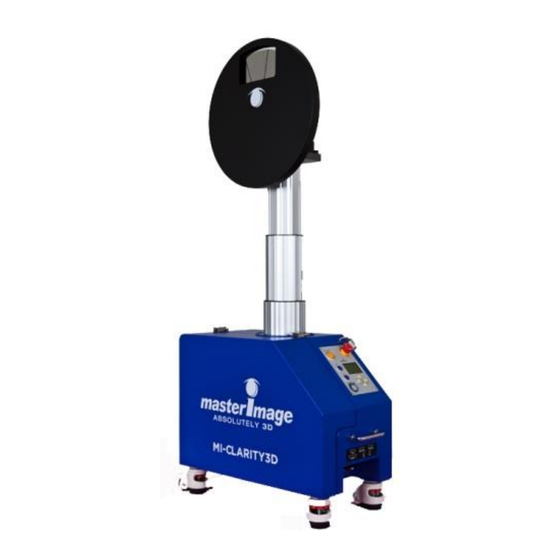
Page 10: System Overview
User Manual | MI-CLARITY3D SA User Manual | MI-CLARITY3D User Manual | MI-CLARITY3D 4. System Overview 4.1. Key Product Components Filter Head Assembly & Polarization Filter Disk (PFD) Up/Down Lifting Column System Control Panel I/O Ports for Synchronization & Automation... -
Page 11: Control Panel
User Manual | MI-CLARITY3D SA User Manual | MI-CLARITY3D User Manual | MI-CLARITY3D 4.2. Control Panel Run/Stop Button Emergency Stop Button 3D Button: to move the PFD to the pre- The display shows programmed 3D Firmware Version, position. Current Operating State and Time. -
Page 12: Installation And Configuration
User Manual | MI-CLARITY3D SA User Manual | MI-CLARITY3D User Manual | MI-CLARITY3D 5. Installation and Configuration 5.1. Unpacking the MI-CLARITY3D 1. Inspect the MI-CLARITY3D crate for any external damage. 2. Carefully remove the crate fasteners, and top and sides of crate using an 8mm socket and power tools. -
Page 13: Unpacking And Preparing The Mi-Clarity3D Rolling Wheels
User Manual | MI-CLARITY3D SA User Manual | MI-CLARITY3D User Manual | MI-CLARITY3D 5.1.1. Unpacking and preparing the MI-CLARITY3D rolling wheels The unit is shipped with the rolling wheels locked. After unpacking, turn the orange rings in the wheel assembly to the left (clockwise) in order to raise the locking pads and allow the unit to be rolled easily. -
Page 14: Orientation 2 - Standard Left
User Manual | MI-CLARITY3D SA User Manual | MI-CLARITY3D User Manual | MI-CLARITY3D Projection Projection Lens Lens Max. 2” extension Standard Right Orientation Standard Right Orientation -- Extended 5.2.2. Orientation 2 – Standard Left With overhanging lenses, as commonly found in Christie projectors, the system may be set with the control panel facing the left side of the projector in order to be more convenient to the operator or to deal with floor space issues. -
Page 15: Orientations 3 & 4 - Reversed Filter Head Right And Left
User Manual | MI-CLARITY3D SA User Manual | MI-CLARITY3D User Manual | MI-CLARITY3D Projection Lens Base Plate: Max.2” extension Standard Left Orientation 5.2.3. Orientations 3 & 4 – Reversed Filter Head Right and Left In rare cases where the lens, projector, floor space or port window do not allow for... -
Page 16: Positioning The Mi-Clarity3D
User Manual | MI-CLARITY3D SA User Manual | MI-CLARITY3D User Manual | MI-CLARITY3D Projection Projection Lens Lens 5.3. Positioning the MI-CLARITY3D 1. Position the MI-CLARITY3D centered with the projector lens and adjust the PFD height using Up arrow switch on the control panel. - Page 17 User Manual | MI-CLARITY3D SA User Manual | MI-CLARITY3D User Manual | MI-CLARITY3D Note: This switch can only be used when the system is in READY status. When the Up arrow switch is pressed and held, the up motion of the filter head assembly continues to move until the switch is released.
-
Page 18: Locking The Mi-Clarity3Ds Wheels In Place
User Manual | MI-CLARITY3D SA User Manual | MI-CLARITY3D User Manual | MI-CLARITY3D 3. Once the position has been adjusted, store this as the 3D Position (as described in Setting a 3D Position, page 30). 5.3.2. Locking the MI-CLARITY3Ds wheels in place Lock down all four of the base wheels by lowering the foot pads. -
Page 19: Releasing The Footpads To Move The Mi-Clarity3D
User Manual | MI-CLARITY3D SA User Manual | MI-CLARITY3D User Manual | MI-CLARITY3D 5.3.3. Releasing the footpads to move the MI-CLARITY3D Turn the orange ring to the left (clockwise) to raise each footpad to release it and move the MI-CLARITY3D. - Page 20 User Manual | MI-CLARITY3D SA User Manual | MI-CLARITY3D User Manual | MI-CLARITY3D In this condition it is important that the PFD itself is refitted the opposite way maintaining the polarizing material facing the screen. (See Orienting the MI-CLARITY3D in front of...
- Page 21 User Manual | MI-CLARITY3D SA User Manual | MI-CLARITY3D User Manual | MI-CLARITY3D Christie Series II file settings for external server playback Note: The Christie projectors should have the field 3D Sync Input Mode set to Use line interleave (First line = Left, second line = right).
-
Page 22: Imb Configuration Settings
User Manual | MI-CLARITY3D SA User Manual | MI-CLARITY3D User Manual | MI-CLARITY3D 5.4.2. IMB Configuration Settings Projector configuration settings when using an IMB (Integrated Media Block) are slightly different; an example of this is given below for a Christie projector and a Doremi IMB. The changes are highlighted in bold. -
Page 23: Basic Operation Of The Mi-Clarity3D
User Manual | MI-CLARITY3D SA User Manual | MI-CLARITY3D User Manual | MI-CLARITY3D 6. Basic Operation of the MI-CLARITY3D Note: In order to prevent accidental operation, press and hold all function buttons for more than 2 seconds for the system to respond. -
Page 24: Move Up And Down The Pfd
User Manual | MI-CLARITY3D SA User Manual | MI-CLARITY3D User Manual | MI-CLARITY3D 6.2. Move Up and Down the PFD 1. In order to position the PFD in front of the projector lens, push the UP arrow button to move the FHA in an upwards direction or the DOWN arrow button for downwards until the PFD is aligned with the projector lens. -
Page 25: Menu Structure With Default Conditions
User Manual | MI-CLARITY3D SA User Manual | MI-CLARITY3D User Manual | MI-CLARITY3D 7. Menu Structure with Default Conditions Level Level Level Level CLOCK [MMM] [DD] [YYYY] [HH] : [DD] : [SS] [CANCEL] [SAVE] Set the local date and time. - Page 26 User Manual | MI-CLARITY3D SA User Manual | MI-CLARITY3D User Manual | MI-CLARITY3D Level Level Level Level >1 AUTOMATION 1. MANUAL REFERENCE Hz 2. GPIO OLD: mmm 3. RS-232C NEW: [MMM] 4. RS-422 [CANCEL] [SAVE] 5. 3D PORT 6. ETHERNET >1...
- Page 27 User Manual | MI-CLARITY3D SA User Manual | MI-CLARITY3D User Manual | MI-CLARITY3D Level Level Level Level Diagnose the system status including communication to FPGA, EEPROM, and communication to Servo pack. *mm: Ok or NG >1 >1 1.PASSWORD [OFF]* SET PASSWORD PASSWORD >2...
- Page 28 User Manual | MI-CLARITY3D SA User Manual | MI-CLARITY3D User Manual | MI-CLARITY3D Level Level Level Level SET FACTORY Perform Performing a Factory Reset? a Factory Reset! Wait a second… [CANCEL] [OK] Reset all user entered information to the factory condition.
-
Page 29: Detailed Setup And Configuration Of The Mi-Clarity3D
User Manual | MI-CLARITY3D SA User Manual | MI-CLARITY3D User Manual | MI-CLARITY3D 8. Detailed Setup and Configuration of the MI-CLARITY3D 8.1. Setting the Clock Note: The Factory Default setting is JAN 01 2011 00:00:00. 1. To set the local time and date on the system from the standby condition, press and hold the MENU key. -
Page 30: Setting A 3D Position
User Manual | MI-CLARITY3D SA User Manual | MI-CLARITY3D User Manual | MI-CLARITY3D column goes down to bottom position, then goes up some distance, and then goes down to bottom position. After finishing adjustment of the lifting column zero position, SETUP screen automatically displays. -
Page 31: Moving Fha To A Predetermined 3D Position
User Manual | MI-CLARITY3D SA User Manual | MI-CLARITY3D User Manual | MI-CLARITY3D 8.3.1. Moving FHA to a Predetermined 3D Position 1. To move the FHA to a predetermined 3D position from the standby condition, press and hold the 3D button. -
Page 32: Moving Fha To A Predetermined 2D Position
User Manual | MI-CLARITY3D SA User Manual | MI-CLARITY3D User Manual | MI-CLARITY3D value. 7. Press and hold the ENTER key on selecting OK to return to the SETUP screen after saving new 2D position value. 8.4.1. Moving FHA to a Predetermined 2D Position 1. -
Page 33: Setting Internal Sync Source Frequency
User Manual | MI-CLARITY3D SA User Manual | MI-CLARITY3D User Manual | MI-CLARITY3D SYNC SOURCE shows the current synchronization input port in the list. The selected option is indicated by the asterisk *. 4. Press the UP or DOWN key to select previous or next sync source in the list. -
Page 34: Selecting An Automation Source
User Manual | MI-CLARITY3D SA User Manual | MI-CLARITY3D User Manual | MI-CLARITY3D 8.6. Selecting an Automation Source Note: The Factory Default setting is Manual. Options are available to automate the control of the MI-CLARITY3D for both 2D and 3D movie presentation. -
Page 35: Setting Pfd Home Position
User Manual | MI-CLARITY3D SA User Manual | MI-CLARITY3D User Manual | MI-CLARITY3D 8.7. Setting PFD Home Position IMPORTANT: PFD Home Position adjustment is required at installation, after PFD replacement or Factory Default reset. It is necessary to teach the system the 3D synchronization position for the PFD 1. -
Page 36: Adjusting 3D Phase
User Manual | MI-CLARITY3D SA User Manual | MI-CLARITY3D User Manual | MI-CLARITY3D 8.8. Adjusting 3D Phase CAUTION: While it is possible to make adjustments to the 3D PHASE angle within the MI-CLARITY3D, this is not usually required or recommended. -
Page 37: Setting The Menu Password
User Manual | MI-CLARITY3D SA User Manual | MI-CLARITY3D User Manual | MI-CLARITY3D 4. Press LEFT or RIGHT key to select CANCEL or OK. 5. Press and hold the ENTER key on selecting CANCEL to return to the SETUP screen without diagnosing the system. - Page 38 User Manual | MI-CLARITY3D SA User Manual | MI-CLARITY3D User Manual | MI-CLARITY3D The display shows the current status of Password on/off. 2. Press UP or DOWN key to turn on or off password protection. 3. Press LEFT or RIGHT key to select CANCEL, SAVE or NEW value.
- Page 39 User Manual | MI-CLARITY3D SA User Manual | MI-CLARITY3D User Manual | MI-CLARITY3D 6. Press UP or DOWN key to select a digit, CANCEL, or OK value. 7. Press and hold the ENTER key on selecting any digit, to select 4-digit password.
-
Page 40: Ethernet Configuration
User Manual | MI-CLARITY3D SA User Manual | MI-CLARITY3D User Manual | MI-CLARITY3D 8.11. Ethernet Configuration Note: Factory Default settings are: IP= 192.168.000.101 SUBNET MASK= 255.255.255.000 GATEWAY= 192.168.000.001 PORT NUMBER= 5000 The items that require configuration are IP, SUBNET MASK, GATEWAY and PORT. - Page 41 User Manual | MI-CLARITY3D SA User Manual | MI-CLARITY3D User Manual | MI-CLARITY3D To Set the Subnet Mask 1. Press ENTER key on selecting SUBNET MASK to change Subnet Mask address. The display shows the current Subnet Mask address. 2. Press UP or DOWN key to increment or decrement the selected value.
-
Page 42: Performing A Factory Reset
User Manual | MI-CLARITY3D SA User Manual | MI-CLARITY3D User Manual | MI-CLARITY3D To Set the Port Number 1. Press ENTER key on selecting PORT NUMBER to change the Port Number. The display shows the current Port Number. 2. Press UP or DOWN key to increment or decrement each digit individually to set the desired value. -
Page 43: Servo Pack Parameter Information
User Manual | MI-CLARITY3D SA User Manual | MI-CLARITY3D User Manual | MI-CLARITY3D 7. After completing a factory reset, LIFT ZERO SET screen shows automatically. Press OK to accept this automatic setting. Note: For eliminating accumulated position error of lifting column, adjust lifting column zero position after performing a factory reset. -
Page 44: System Information
User Manual | MI-CLARITY3D SA User Manual | MI-CLARITY3D User Manual | MI-CLARITY3D The display shows the index of recent log, time stamp, log name, parameter 1, and parameter 2. 4. Press UP or DOWN key to change the log INDEX. -
Page 45: Installation Checklist
User Manual | MI-CLARITY3D SA User Manual | MI-CLARITY3D User Manual | MI-CLARITY3D 9. Installation Checklist Item Check Remarks Determine spacing and position of the MI- CLARITY3D in front of the Projector Check that the polarizing filter is on the screen side of the disk, and silver screen and non- depolarizing port glass are installed. -
Page 46: Maintenance
User Manual | MI-CLARITY3D SA User Manual | MI-CLARITY3D User Manual | MI-CLARITY3D 10. Maintenance WARNING: To avoid electric shock, ensure the power switch is off and unplug the power cord prior to cleaning the PFD Injury may result while working near moving parts. Do not power up the system to spin the PFD while cleaning the PFD. - Page 47 User Manual | MI-CLARITY3D SA User Manual | MI-CLARITY3D User Manual | MI-CLARITY3D 3. Unfasten the PFD by removing the twelve outer screws holding it in place followed by the center PFD position guide and screw. 1. PFD 2. PFD Position Guide 3.
- Page 48 User Manual | MI-CLARITY3D SA User Manual | MI-CLARITY3D User Manual | MI-CLARITY3D 4. Carefully remove the PFD from the drive hub. 5. Set the old PFD aside and immediately mark it with a permanent marker as follows: “Used, removed on [today’s date]”.
- Page 49 User Manual | MI-CLARITY3D SA User Manual | MI-CLARITY3D User Manual | MI-CLARITY3D Last, peel off the sticky film from the clear side of the filter. 8. Orient the disk with the filter material facing the correct side for your theatre. The PFD is labeled to show “This side is towards screen” and “This side is towards projector”.
- Page 50 User Manual | MI-CLARITY3D SA User Manual | MI-CLARITY3D User Manual | MI-CLARITY3D 10. To secure the PFD, do the following: Insert the countersunk PFD Position Guide Screw. Do not tighten at this time. Insert each of the 12 PFD Outer Screws but do not tighten. Ensure flat and spring washers are fitted to each screw.
- Page 51 User Manual | MI-CLARITY3D SA User Manual | MI-CLARITY3D User Manual | MI-CLARITY3D 11. Replace the PFD cover by carefully placing it over the PFD. Replace all eight screws loosely. Hand-tighten the screws firmly from the top to the bottom.
-
Page 52: Cleaning The Pfd
User Manual | MI-CLARITY3D SA User Manual | MI-CLARITY3D User Manual | MI-CLARITY3D 10.2. Cleaning the PFD 10.2.1. Materials Required To ensure that PFD is cleaned safely, use materials as specified. Use only approved micro fiber type polishing cloths. These cloths feel extra soft to the touch with absolutely no abrasive texture. - Page 53 User Manual | MI-CLARITY3D SA User Manual | MI-CLARITY3D User Manual | MI-CLARITY3D 3. Hold the PFD steady with one hand, and while applying gentle pressure, carefully wipe the PFD with the cleaning cloth. Wipe from the center of the PFD to the outer edge only. See the illustration below.
- Page 54 User Manual | MI-CLARITY3D SA User Manual | MI-CLARITY3D User Manual | MI-CLARITY3D For areas that are difficult to clean: Isopropyl alcohol is the recommended cleaning solution. If using any other solution for the first time on the PFD, apply a small amount of solution to the cloth. Then wipe a small area near the PFD hub (out of the picture area) and inspect the results carefully for any surface damage.
-
Page 55: Simple Troubleshooting
User Manual | MI-CLARITY3D SA User Manual | MI-CLARITY3D User Manual | MI-CLARITY3D 11. Simple Troubleshooting 11.1. Button LED Notification The system buttons contain LEDs that display system status. 1) yellow LED on RUN/STOP button, 2) blue LED on 3D button, blue LED on 2D button, and green LED on POWER button. -
Page 56: Fuses
User Manual | MI-CLARITY3D SA User Manual | MI-CLARITY3D User Manual | MI-CLARITY3D 11.2. Fuses If the system is plugged in and the MI-CLARITY3Ds LCD display on the control panel does not light up when the power breaker is switched ON and the Power button has been pressed, then it is necessary to check the main power fuses. -
Page 57: Servopak Correct Status Indication
User Manual | MI-CLARITY3D SA User Manual | MI-CLARITY3D User Manual | MI-CLARITY3D 5. Check the fuses for continuity. Open (burned) fuses can be replaced with time delay fuses of either FNM-10 or FNQ-R-10 type. FNM-10 Type Fuse 6. Install the good fuses and any replacements and close the fuse holders and base door. -
Page 58: Servopak Error Status Indication
User Manual | MI-CLARITY3D SA User Manual | MI-CLARITY3D User Manual | MI-CLARITY3D System Standby Indication System Running Indication 11.4. Servopak Error Status Indication The images below indicate particular Servopak error conditions and the respective corrective action that should be taken. -
Page 59: Cn1 Not Connected
User Manual | MI-CLARITY3D SA User Manual | MI-CLARITY3D User Manual | MI-CLARITY3D The display will show the E-Stop indication along with the Run/Stop, 3D & 2D buttons all flashing. To recover from this condition check the operating situation is safe, release the E-... -
Page 60: Cn2 Not Connected
User Manual | MI-CLARITY3D SA User Manual | MI-CLARITY3D User Manual | MI-CLARITY3D 11.4.3. CN2 Not Connected The display will also show an error similar to that in the image above. If this situation is seen, power off the system, check the connection of the CN2 cable, reinsert as necessary and power on the system. -
Page 61: Firmware Upgrading Process For Mi-Clarity3D Series
User Manual | MI-CLARITY3D SA User Manual | MI-CLARITY3D User Manual | MI-CLARITY3D 12. Firmware Upgrading Process for MI-CLARITY3D Series Note: The latest firmware and associated utility tools can be downloaded from the MasterImage FTP site: ftp://masterimage3d.us L: mi3dguest1 P: M!3DuploadASIA The current system firmware version can be seen on the LCD display when the system is in Standby. - Page 62 User Manual | MI-CLARITY3D SA User Manual | MI-CLARITY3D User Manual | MI-CLARITY3D 6. Select new firmware file from the location it was saved on your computer, having the *.dfu file extension in the Open dialog box. Then click the Open button to upgrade firmware.
- Page 63 User Manual | MI-CLARITY3D SA User Manual | MI-CLARITY3D User Manual | MI-CLARITY3D 8. Click the Yes button if the utility shows a confirmation dialog such as the example below, after making sure the correct file has been selected for upgrade.
-
Page 64: Upgrade Fpga Binary
User Manual | MI-CLARITY3D SA User Manual | MI-CLARITY3D User Manual | MI-CLARITY3D 10. Turn off the MI-CLARITY3D AC Power Breaker and then turn it on again (“cycle the power”). 11. Press the MI-CLARITY3D POWER button and check the new version number on the System Version screen, as shown below. - Page 65 User Manual | MI-CLARITY3D SA User Manual | MI-CLARITY3D User Manual | MI-CLARITY3D 4. Click the Setup button to open the Setup Dialog window. 5. Select the COM Port number of STMicroelectonices Virtual COM Port that you checked in step 2 and click OK.
- Page 66 User Manual | MI-CLARITY3D SA User Manual | MI-CLARITY3D User Manual | MI-CLARITY3D 8. Click the Open button to open the Open dialog. 9. Select new FPGA binary file having ‘*.dat’ file extension in the list of Open dialog box and click the Open button.
- Page 67 User Manual | MI-CLARITY3D SA User Manual | MI-CLARITY3D User Manual | MI-CLARITY3D One the upgrade process is complete, the system will have completed an automatic FACTORY RESET, therefore it will be necessary to reset the following items: LIFT ZERO – This process will be automatically prompted. See 8.2, Setting the Lifting Column Zero Position, on page 29.
-
Page 68: Product Specifications
User Manual | MI-CLARITY3D SA User Manual | MI-CLARITY3D User Manual | MI-CLARITY3D 13. Product Specifications Category Specification Model Name [200 ~ 230V] MI-CLARITY3D SA [100 ~ 120V] MI-CLARITY3D SA(T) Size and Weight Projection Height (Max/Min): 1370/870 mm (54.6/34.3 in.) Width: 580 mm (22.8 in.) - Page 69 User Manual | MI-CLARITY3D SA User Manual | MI-CLARITY3D User Manual | MI-CLARITY3D Dimensions in inches. Dimensions in millimeters. © MASTERIMAGE 3D, Inc.
-
Page 70: Appendix A - Turning The Filter Head Assembly (Fha)
User Manual | MI-CLARITY3D SA User Manual | MI-CLARITY3D User Manual | MI-CLARITY3D 14. Appendix A – Turning the Filter Head Assembly (FHA) The following steps describe removing and turning the FHA in order to orient the system in a non-standard configuration. - Page 71 User Manual | MI-CLARITY3D SA User Manual | MI-CLARITY3D User Manual | MI-CLARITY3D 7. Move system in front of projector. Make various adjustments to PFD position according to standard installation procedures by moving the motor up and down (see 5.3 on page 16) and moving the bracket in its slide in order to position the filter close...
-
Page 72: Appendix B - Mi-Clarity3D Automation
User Manual | MI-CLARITY3D SA User Manual | MI-CLARITY3D User Manual | MI-CLARITY3D 15. Appendix B – MI-CLARITY3D Automation Table B-1. GPIO Automation DSUB9(GPIO) Comm. DSUB37 Direc- Pin name Description Comments tion number number No connection PRJ_COM_nRUN 12(+) PFD RUN command... - Page 73 User Manual | MI-CLARITY3D SA User Manual | MI-CLARITY3D User Manual | MI-CLARITY3D © MASTERIMAGE 3D, Inc.
- Page 74 User Manual | MI-CLARITY3D SA User Manual | MI-CLARITY3D User Manual | MI-CLARITY3D Table B-2. TTL Automation DSUB9(TTL) Comm. DSUB9 Direc- Description Comments Pin name tion number number No connection Transmitter RS-232 Driver (ST3232ECTR) Receiver (Max :±25V) No connection...
-
Page 75: Ethernet Automation
User Manual | MI-CLARITY3D SA User Manual | MI-CLARITY3D User Manual | MI-CLARITY3D Table B-4. 3D Port Automation DSUB15(3D-Port) Comm. DSUB15 Direc- Description Comments Pin name tion number number V12A +12V Max:1A Ground Ground AUTO2_TXD Transmitter RS-232 Driver ... -
Page 76: Doremi Server
User Manual | MI-CLARITY3D SA User Manual | MI-CLARITY3D User Manual | MI-CLARITY3D 15.1.1. Doremi Server 1. Within the server menu, open Device Manager (Menu > DTS Digital Cinema > Device Manager) 2. Press the Add button and the list of devices will display (shown right). - Page 77 User Manual | MI-CLARITY3D SA User Manual | MI-CLARITY3D User Manual | MI-CLARITY3D It is now possible to create the macro files to enable the server to control the MI-CLARITY3D. The files required are: MasterImage Start, MasterImage Stop, MasterImage 2D, MasterImage 3D and MasterImage Up/Down Stop. These are created in the Macro Editor option of the server menu.
- Page 78 User Manual | MI-CLARITY3D SA User Manual | MI-CLARITY3D User Manual | MI-CLARITY3D 3. To insert an action for each newly created macro, select the macro in question from the list within the Macro window and press the Insert a New Action button which will become available.
- Page 79 User Manual | MI-CLARITY3D SA User Manual | MI-CLARITY3D User Manual | MI-CLARITY3D 5. In this window, choose the device MasterImage from the Device name dropdown list and type in the Message label of MasterImage Start. Ensure the Message type is Text and type Start\n in the Message box.
- Page 80 User Manual | MI-CLARITY3D SA User Manual | MI-CLARITY3D User Manual | MI-CLARITY3D In future versions of Doremi software updates, the MasterImage macros will be included in a file named MasterImage_cueslib. This will remove the requirement for the information to be entered manually as described in the above steps.
-
Page 81: Qube Server
User Manual | MI-CLARITY3D SA User Manual | MI-CLARITY3D User Manual | MI-CLARITY3D 15.1.2. Qube Server To create automation macros for the MI-CLARITY3D in the Qube server it is necessary to edit two XML files within the server’s configuration. The files in question are located in the path C:/Program Files/Qube Cinema/XP and are named automationdevices.xml and automationcues.xml... - Page 82 User Manual | MI-CLARITY3D SA User Manual | MI-CLARITY3D User Manual | MI-CLARITY3D 2. Complete the fields with the details of the MasterImage MI-CLARITY3D where: “Device “MasterImage” Name” “Device “Qube.Automation.streamdevice.TCP” Class” “file name of the “MasterImage.xml” device” “addess value” MI-CLARITY3D Assigned IP Address “port...
- Page 83 User Manual | MI-CLARITY3D SA User Manual | MI-CLARITY3D User Manual | MI-CLARITY3D </Instructions> </Method> <Method name="PFDStop"> <Instructions> <Send>PFD Stop
</Send> </Instructions> </Method> </StreamDevice> The symbols 
 are necessary at the end of each command to close the command in the xml structure.
-
Page 84: Gdc Server
User Manual | MI-CLARITY3D SA User Manual | MI-CLARITY3D User Manual | MI-CLARITY3D <Cue name="Up/Down Stop"> <Actions> <InvokeMethod name="PFDStop" device="MasterImage"/> </Actions> </Cue> Once this file has been edited and saved the graphical interface of the Qube server will display the new cues that can be selected for future playlist creation. - Page 85 User Manual | MI-CLARITY3D SA User Manual | MI-CLARITY3D User Manual | MI-CLARITY3D 2. Once you have logged on, press the Automation button found on the General tab. © MASTERIMAGE 3D, Inc.
- Page 86 User Manual | MI-CLARITY3D SA User Manual | MI-CLARITY3D User Manual | MI-CLARITY3D The MI-CLARITY3D must be added as a device within the GDC server configuration. 3. Select the Devices tab and press the Add button. The following screen will display:...
- Page 87 User Manual | MI-CLARITY3D SA User Manual | MI-CLARITY3D User Manual | MI-CLARITY3D 4. Name the new device MasterImage, and ensure the Type selection is set to NETWORKSOCKET, then press OK. 5. In the next screen, enter the configuration settings for the MI-CLARITY3D IP Address and Port Number.
- Page 88 User Manual | MI-CLARITY3D SA User Manual | MI-CLARITY3D User Manual | MI-CLARITY3D 9. Press the Add button to create a new event. In this case, name the event START. 10. Press the Enter button and enter the command value for the event. Again in this case, START.
- Page 89 User Manual | MI-CLARITY3D SA User Manual | MI-CLARITY3D User Manual | MI-CLARITY3D 11. Press the Enter button to save this change, then go back and make entries for the remaining four macros that are required. Event Name STOP Enter Value STOP...
- Page 90 User Manual | MI-CLARITY3D SA User Manual | MI-CLARITY3D User Manual | MI-CLARITY3D 14. Once all event actions have been created press the Save button followed by Yes. © MASTERIMAGE 3D, Inc.
-
Page 91: Appendix C - Installation Record
User Manual | MI-CLARITY3D SA User Manual | MI-CLARITY3D User Manual | MI-CLARITY3D 16. Appendix C – Installation Record The form below and on the next page is an example of the installation record form to be filled out once the MI-CLARITY3D has been set up and configured. -
Page 92: Appendix D - Periodic Maintenance
User Manual | MI-CLARITY3D SA User Manual | MI-CLARITY3D User Manual | MI-CLARITY3D 17. Appendix D – Periodic Maintenance The table below show the least regular maintenance points carried out by operator in cinema. To guarantee reliable system operation, weekly, monthly and yearly routine maintenance actions should be conducted like manual description or other technical bulletin that MASTERIMAGE released. -
Page 93: Appendix E - Check The Stm Virtual Com Port Number
User Manual | MI-CLARITY3D SA User Manual | MI-CLARITY3D User Manual | MI-CLARITY3D 18. Appendix E – Check the STM Virtual COM Port Number You can see the virtual COM Port number after connecting MI-CLARITY3D to your PC. Run the Control Panel in your PC.